-
SINGLE ACTING OR DOUBLE ACTING CYLINDERS
- The valving allows for use of single or double acting cylinders. The cylinders are controlled in two banks of 4 per power pack.
-
NUMBER OF CYLINDERS
- Each power pack can control up to eight cylinders, or groups of cylinders. The power packs can be linked together for control by one master unit. Up to 16 power packs can be ‘daisy chained’ together, giving up to 128 individually controlled valve points. These valve points can control one cylinder or a group of cylinders.
-
CYLINDER LOCATIONS
- The system can store the ‘X’, ‘Y’ and ‘Z’ co-ordinates for each cylinder, as required by lift type. Not all lift types require all the positional data.
-
NUMBER OF SLAVE SYSTEMS
- Each additional power pack controlling eight cylinders is designated as a slave system. The master unit can control up to 15 additional 8 valve power packs, giving a total of up to 128 individually controlled cylinders or groups of cylinders.
-
PRESSURE TRANSDUCERS
- The DURAPAC SLS system has available pressure transducers for control of individual cylinders, as well as total cylinder load and pressure. This is used in the ‘Centre of Mass’ function, for load measuring and for pressure driven load control.
-
CYLINDER AREAS AND STROKES
- To calculate the load per cylinder and the correct displacement, the program needs the cylinder piston and rod effective area, and the stroke. This is selected from drop down menus for DURAPAC cylinders, or manual entry of the information for other cylinders.
-
TYPES OF LIFT
- a. CORRECTION LIFT. Where the lifting surface needs to be adjusted to bring it to a plane. An example would be one corner of a building that has dropped. Each cylinder is given its’ start and finish position for the lift. In this case, ‘X’ and ‘Y’ position data for the cylinders are not required.
- b. TILTING LIFT. Where the item being lifted needs to be set to a different angle, but the lifting plane does not need correction. For this type of lift, ‘X’, ‘Y’ and ‘Z’ data are required for each cylinder.
- c. UNIFORM LIFT. Where the stroke of all cylinders is the same. This is the simplest lift case, and does not require ‘X’ and ‘Y’ location data.
- d. MANUAL LIFT. Where each cylinder is manually jogged to the required position. This may be used as part of the set-up for an automated lift, or as a lift adjustment feature.
- e. PRESSURE LOAD. Where each cylinder advances until a certain pressure is reached. Used to pre-load the structure and lifting point to minimise the variance between the cylinder displacement and the load displacement. Also used when applying a set or stepped load as in the testing of pylons, anchors etc. There are up to 5 load increments (including load reduction), duration of each in minutes, and tolerance for the applied load. In this mode, the cylinder live data field shows the current pressure or tonnage.
-
PRESSURE LIMITS
- For an individual cylinder or for all cylinders. This can be entered as load or pressure with the alternative value being auto filled based on the cylinder data that has been entered.
-
MAXIMUM LIFT ‘SPEED’
- This is the valving switching on and off to limit the displacement per unit time rather than the actual cylinder speed. The absolute cylinder speed is a product of pump flow rate and cylinder effective area. As neither of these is variable within the program, the only control available is to open and close the valve to limit the displacement of the cylinder over a given time. You can use manual flow control to slow the lift rate, and there is the extra cost option of a VSD to vary pump output.
-
LOAD AND CYLINDER DISPLACEMENT VARIANCE CONTROL
- The DURAPAC DSL system has available two linear transducers per lifting point. One for monitoring the cylinder displacement, and one for the load displacement. As there is the possibility that the loading of the cylinder may cause some undefined amount of sinking of the cylinder, or deformation of the load, the operator will be able to put a limit on the difference between these two displacements.
-
CENTRE OF MASS
- The DURAPAC DSL system is able to describe a boundary using either two (‘X’,’Y’) points (diagonal corners of a rectangle), or a centre point and radius (polar), to define an area outside of which the centre of mass line of action must not move. This is a safety feature for use in the levelling of tall or uneven loads.
-
DATA RECORDING
- Recording of data (displacement, pressure) is available over an operator defined time base. This data can be down loaded and exported into Microsoft Excel for further analysis and for record keeping.
Home / For Hire / Sync Lifting System / Durapac Syncmaster Lifting System
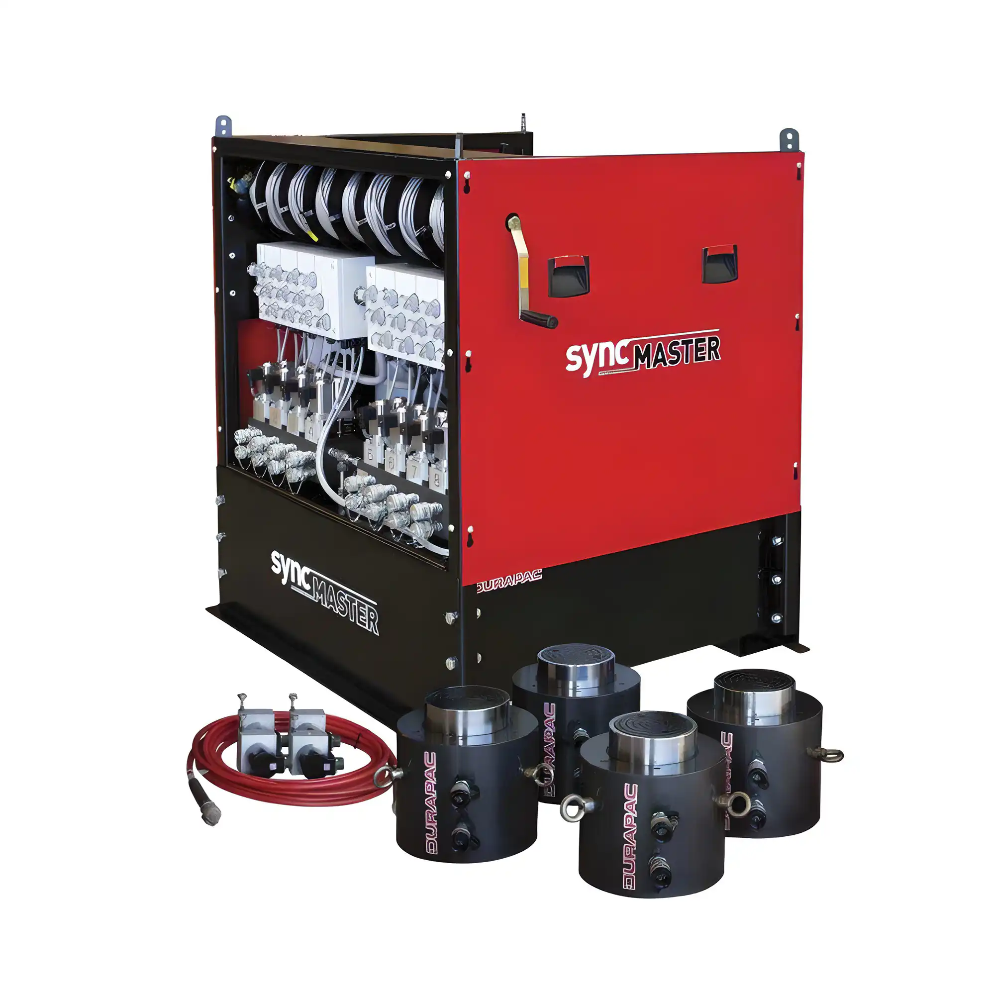
Durapac Syncmaster Lifting System
The Durapac Syncmaster Synchronous Lifting System is a computer controlled hydraulic lifting system that provides a safe lifting system for your large scale engineering and maintenance projects.
- The DSL-series synchronous lift system allows for up to 16 power packs to be controlled by one master unit, giving a maximum of 128 individually controlled cylinder points.
- Note that this is the control box only and each job requires a tailored solution for your lifting requirements. Our team can assist you with specifying the full system for your unique project.
For Hire Rates please click the Enquire button below, or call the team on 0800 48 2000.
More Information
Related Hire Products
No related Hire Products found.